- Products
- Market Solutions & Services
- Insight
- Tools & Resources
- About Nexans Australia
- Search
- Contact us
- Compare
- Sign in
.png/jcr:content/Untitled%20design%20(8).jpg)
VAROLEX® VSD 3C+3E 90°C - Flexible for Fixed Application
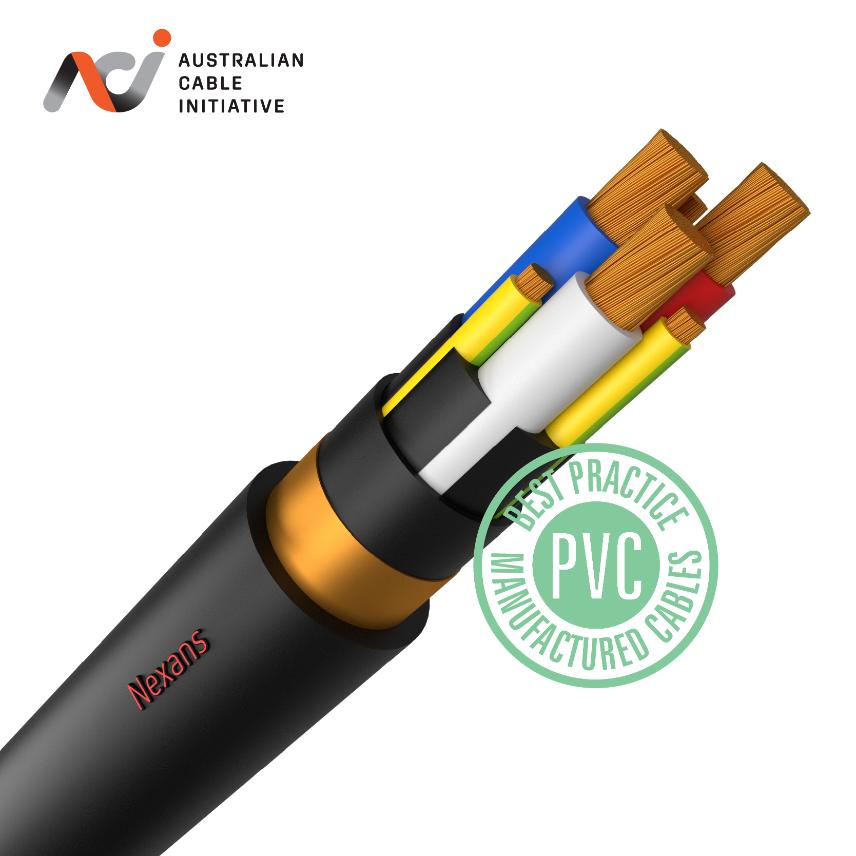
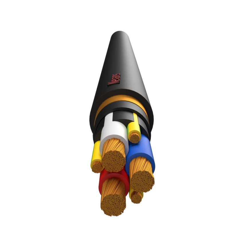
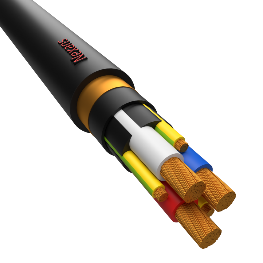
VAROLEX® VSD 3C+3E 90°C - Flexible for Fixed Application
3C + 3E flexible copper conductor, 0.6/1kV X-90 insulated, PVC bedded, copper tape screened, PVC sheathed to AS/NZS 5000.1, 90°C
Read more3X1.5mm2 + E Flex Varolex Black
Nexans ref. FTDR04AA003CXRJ
- Packaging: Cut to length (m)
- Combined earth size section: 1.5 mm²
- Conductor cross-section: 1.5 mm²
- Number of earth cores: 1
- Maximum Pulling Tension: 0.1 kN
- Minimum Bend Radius - During Installation (under Tension): 245 mm
- Minimum Bend Radius - Installed: 160 mm
3X2.5mm2 + E Flex Varolex Black
Nexans ref. FTDR05AA003CXRJ - Country ref. FTDR05AA003CXRJ
- Packaging: Cut to length (m)
- Combined earth size section: 2.5 mm²
- Conductor cross-section: 2.5 mm²
- Number of earth cores: 1
- Maximum Pulling Tension: 0.2 kN
- Minimum Bend Radius - During Installation (under Tension): 265 mm
- Minimum Bend Radius - Installed: 175 mm
3X4mm2 + 3E Flex Varolex Black
Nexans ref. FTDR06AA003CXRJ - Country ref. FTDR06AA003CXRJ
- Packaging: Cut to length (m)
- Combined earth size section: 4.5 mm²
- Conductor cross-section: 4 mm²
- Number of earth cores: 3
- Maximum Pulling Tension: 0.2 kN
- Minimum Bend Radius - During Installation (under Tension): 310 mm
- Minimum Bend Radius - Installed: 210 mm
3X6mm2 + 3E Flex Varolex Black
Nexans ref. FTDR07AA003CXRJ - Country ref. FTDR07AA003CXRJ
- Packaging: Cut to length (m)
- Combined earth size section: 4.5 mm²
- Conductor cross-section: 6 mm²
- Number of earth cores: 3
- Maximum Pulling Tension: 0.4 kN
- Minimum Bend Radius - During Installation (under Tension): 325 mm
- Minimum Bend Radius - Installed: 215 mm
3X10mm2 + 3E Flex Varolex Black
Nexans ref. FTDX01AA003CXRJ - Country ref. FTDX01AA003CXRJ
- Packaging: Cut to length (m)
- Combined earth size section: 4.5 mm²
- Conductor cross-section: 10 mm²
- Number of earth cores: 3
- Maximum Pulling Tension: 0.6 kN
- Minimum Bend Radius - During Installation (under Tension): 345 mm
- Minimum Bend Radius - Installed: 230 mm
3X16mm2 + 3E Flex Varolex Black
Nexans ref. FTDX02AA003CXRJ - Country ref. FTDX02AA003CXRJ
- Packaging: Cut to length (m)
- Combined earth size section: 7.5 mm²
- Conductor cross-section: 16 mm²
- Number of earth cores: 3
- Maximum Pulling Tension: 1 kN
- Minimum Bend Radius - During Installation (under Tension): 390 mm
- Minimum Bend Radius - Installed: 260 mm
3X25mm2 + 3E Flex Varolex Black
Nexans ref. FTDX03AA003CXRJ - Country ref. FTDX03AA003CXRJ
- Packaging: Cut to length (m)
- Combined earth size section: 12 mm²
- Conductor cross-section: 25 mm²
- Number of earth cores: 3
- Maximum Pulling Tension: 1.5 kN
- Minimum Bend Radius - During Installation (under Tension): 440 mm
- Minimum Bend Radius - Installed: 295 mm
3X35mm2 + 3E Flex Varolex Black
Nexans ref. FTDX04AA003CXRJ - Country ref. FTDX04AA003CXRJ
- Packaging: Cut to length (m)
- Combined earth size section: 18 mm²
- Conductor cross-section: 35 mm²
- Number of earth cores: 3
- Maximum Pulling Tension: 2.1 kN
- Minimum Bend Radius - During Installation (under Tension): 490 mm
- Minimum Bend Radius - Installed: 325 mm
3X50mm2 + 3E Flex Varolex Black
Nexans ref. FTDX05AA003CXRJ - Country ref. FTDX05AA003CXRJ
- Packaging: Cut to length (m)
- Combined earth size section: 30 mm²
- Conductor cross-section: 50 mm²
- Number of earth cores: 3
- Maximum Pulling Tension: 3 kN
- Minimum Bend Radius - During Installation (under Tension): 565 mm
- Minimum Bend Radius - Installed: 375 mm
3X70mm2 + 3E Flex Varolex Black
Nexans ref. FTDX63AA003CXRJ - Country ref. FTDX63AA003CXRJ
- Packaging: Cut to length (m)
- Combined earth size section: 30 mm²
- Conductor cross-section: 70 mm²
- Number of earth cores: 3
- Maximum Pulling Tension: 4.2 kN
- Minimum Bend Radius - During Installation (under Tension): 645 mm
- Minimum Bend Radius - Installed: 430 mm
3X95mm2 + 3E Flex Varolex Black
Nexans ref. FTDX64AA003CXRJ - Country ref. FTDX64AA003CXRJ
- Packaging: Cut to length (m)
- Combined earth size section: 48 mm²
- Conductor cross-section: 95 mm²
- Number of earth cores: 3
- Maximum Pulling Tension: 4.84 kN
- Minimum Bend Radius - During Installation (under Tension): 725 mm
- Minimum Bend Radius - Installed: 485 mm
3X120mm2 + 3E Flex Varolex Black
Nexans ref. FTDE87AA003CXRJ - Country ref. FTDE87AA003CXRJ
- Packaging: Cut to length (m)
- Combined earth size section: 48 mm²
- Conductor cross-section: 120 mm²
- Number of earth cores: 3
- Maximum Pulling Tension: 5.44 kN
- Minimum Bend Radius - During Installation (under Tension): 815 mm
- Minimum Bend Radius - Installed: 545 mm
3X150mm2 + 3E Flex Varolex Black
Nexans ref. FTDE88AA003CXRJ - Country ref. FTDE88AA003CXRJ
- Packaging: Cut to length (m)
- Combined earth size section: 75 mm²
- Conductor cross-section: 150 mm²
- Number of earth cores: 3
- Maximum Pulling Tension: 6.02 kN
- Minimum Bend Radius - During Installation (under Tension): 905 mm
- Minimum Bend Radius - Installed: 600 mm
3X185mm2 + 3E Flex Varolex Black
Nexans ref. FTDE89AA003CXRJ - Country ref. FTDE89AA003CXRJ
- Packaging: Cut to length (m)
- Combined earth size section: 75 mm²
- Conductor cross-section: 185 mm²
- Number of earth cores: 3
- Maximum Pulling Tension: 6.62 kN
- Minimum Bend Radius - During Installation (under Tension): 995 mm
- Minimum Bend Radius - Installed: 660 mm
3X240mm2 + 3E Flex Varolex Black
Nexans ref. FTDE90AA003CXRJ - Country ref. FTDE90AA003CXRJ
- Packaging: Cut to length (m)
- Combined earth size section: 105 mm²
- Conductor cross-section: 240 mm²
- Number of earth cores: 3
- Maximum Pulling Tension: 7.4 kN
- Minimum Bend Radius - During Installation (under Tension): 1110 mm
- Minimum Bend Radius - Installed: 740 mm
3X300mm2 + 3E Flex Varolex Black
Nexans ref. FTDE91AA003CXRJ - Country ref. FTDE91AA003CXRJ
- Packaging: Cut to length (m)
- Combined earth size section: 150 mm²
- Conductor cross-section: 300 mm²
- Number of earth cores: 3
- Maximum Pulling Tension: 8.2 kN
- Minimum Bend Radius - During Installation (under Tension): 1230 mm
- Minimum Bend Radius - Installed: 820 mm
Description
Description
Standards
-
ProductAS/NZS 1125; AS/NZS 5000.1
- Intended for fixed variable speed drive applications
- 0.6/1kV X-90 insulated,
- 3 core+3 earths,
- PVC bedded,
- Copper tape screened,
- PVC sheathed to AS/NZS 5000.1,
- Class 5 and 6 flexible conductor
*For 1.5mm² & 2.5 mm², split earth not feasible, therefore a single earth conductor is utilised.
Characteristics
Characteristics
Construction characteristics
Construction characteristics
Dimensional characteristics
Dimensional characteristics
Electrical characteristics
Electrical characteristics
Mechanical characteristics
Mechanical characteristics
Usage characteristics
Usage characteristics
Resources
Resources
Documentation
Multicore Flexible - Current carrying capacities three phase (in Amps)
Flexible copper conductor
Maximum conductor temperature: 90°C
Reference ambient temperature: 40°C IN AIR, 25°C IN GROUND
| Conductor cross-section |

|

|

|

|

|

|

|

|

|
|---|---|---|---|---|---|---|---|---|---|
| mm² | Cu | Cu | Cu | Cu | Cu | Cu | Cu | Cu | Cu |
| 1.0 | 16.0 | 15.0 | 12.0 | 8.0 | 14.0 | 11.0 | 7.0 | 23.0 | 17.0 |
| 1.5 | 20.0 | 19.0 | 15.0 | 10.0 | 17.0 | 13.0 | 8.0 | 28.0 | 21.0 |
| 2.5 | 27.0 | 26.0 | 20.0 | 13.0 | 23.0 | 18.0 | 11.0 | 37.0 | 28.0 |
| 4.0 | 36.0 | 34.0 | 27.0 | 17.0 | 29.0 | 24.0 | 15.0 | 49.0 | 36.0 |
| 6.0 | 46.0 | 43.0 | 35.0 | 22.0 | 37.0 | 29.0 | 18.0 | 61.0 | 45.0 |
| 10.0 | 66.0 | 61.0 | 49.0 | 31.0 | 52.0 | 42.0 | 26.0 | 84.0 | 62.0 |
| 16.0 | 87.0 | 81.0 | 65.0 | 41.0 | 67.0 | 53.0 | 33.0 | 108.0 | 79.0 |
| 25.0 | 116.0 | 108.0 | 87.0 | 54.0 | 89.0 | 71.0 | 44.0 | 139.0 | 103.0 |
| 35.0 | 144.0 | 135.0 | 108.0 | 67.0 | 111.0 | 89.0 | 56.0 | 168.0 | 127.0 |
| 50.0 | 182.0 | 170.0 | 136.0 | 0.0 | 136.0 | 109.0 | 0.0 | 206.0 | 155.0 |
| 70.0 | 230.0 | 214.0 | 171.0 | 0.0 | 173.0 | 138.0 | 0.0 | 251.0 | 193.0 |
| 95.0 | 275.0 | 256.0 | 205.0 | 0.0 | 202.0 | 162.0 | 0.0 | 293.0 | 226.0 |
| 120.0 | 327.0 | 303.0 | 242.0 | 0.0 | 242.0 | 194.0 | 0.0 | 337.0 | 266.0 |
| 150.0 | 375.0 | 348.0 | 278.0 | 0.0 | 274.0 | 219.0 | 0.0 | 380.0 | 300.0 |
| 185.0 | 428.0 | 396.0 | 317.0 | 0.0 | 314.0 | 251.0 | 0.0 | 424.0 | 339.0 |
| 240.0 | 511.0 | 472.0 | 378.0 | 0.0 | 379.0 | 303.0 | 0.0 | 493.0 | 402.0 |
| 300.0 | 584.0 | 539.0 | 0.0 | 0.0 | 0.0 | 0.0 | 0.0 | 554.0 | 452.0 |
| 400.0 | 692.0 | 638.0 | 0.0 | 0.0 | 0.0 | 0.0 | 0.0 | 639.0 | 537.0 |
| 500.0 | 794.0 | 730.0 | 0.0 | 0.0 | 0.0 | 0.0 | 0.0 | 716.0 | 602.0 |
|
Unenclosed spaced |
|
Unenclosed touching |
|
Unenclosed and partially surrounded by thermal insulation |
|
Unenclosed and completely surrounded by thermal insulation |
|
Enclosed conduit in air |
|
Enclosed, partially surrounded by thermal insulation |
|
Enclosed, completely surrounded by thermal insulation |
|
Buried direct |
|
Underground Wiring Enclosure |
Our websites
Select your country to find our products and solutions
-
Africa
- Africa
- Ghana
- Ivory Coast
- Morocco
- North West Africa
- Americas
- Asia
- Europe
- Oceania